Saturday 30 April 2011

Some Streampunk Trinkets


Had a request to post more steampunk stuff I have made so here it is


The Design of the Widow in regards to Filigree and cogs is influenced by steampunk and also an offshoot of the jewellery i have been making of late.

Friday 29 April 2011

Les Arcs Snowboarding Video

I had intended to use my DIY Steadicam for this video but it was bad enough carrying around my 60D all over the mountain on my snowboard without carrying the steadicam too.

Thursday 28 April 2011

DIY Steadicam final design

EXTREEEMLY STEADY TOM CAM 5 TO THE 25th

HOW STEADY IS STEADY? TURBO STEADY TECHNOLOGY KICKS YOU IN THE FACE WITH STEADINESS, EXTREEEM STEADY. STEADIER THAN A BOMB DISPOSAL EXPERT PLAYING OPERATION AGAINST A BRAIN SURGEON 
So after some trials with my DIY Steadicam I’m now confident it’s finished, for now.
I had to make a few modifications after each test to resolve new problems that emerged each time. 
One thing i was previously unhappy was the attachment between the universal joint and the threaded bar. After Santa gave me some new metal drill bits i was able to drill through the universal joint and bar to bolt them together, this has stopped the slip that was occurring due to it only being glued. I will be looking for a Universal joint to replace the one i am currently using however as it just doesn’t feel very sturdy. Picture bellow showing universal joint and bolts holding the steadicam together
After the first test shoot it became apparent the rig was too flexible which created bounce in the video so i went about stiffening the whole design. The join between the bracket and the bike mount part was originally two rivets side by side but this allowed movement so i added a third larger rivet bellow the previous two to stiffen the join. The steadicam suffers a lot less from bounce here now.
another problem creating bounce was the fact that the camera was attached to the main body of the steadicam by only one bolt mounted quite far forward, this created a spring like movement on the camera so i added another bracket and bolted it to the back of the adjustable plate to remove any movement arising from the join to the main body. Much of the DIY process has been learning as I go.
the two brackets didnt quite meet up so i had to drill new holes for the 4 bolts holding the two brackets together.
another addition i added previously was a slip ring that controls pan. I also replaced the handle with one length of pvc pipe, the previous handle made from a table top tripod kept slipping in its join and off balancing the steadicam.
Detail of the Adjustment mechanism, it had to perform 2 functions, move with millimetre precision and lock firm in place, as it stands it is for-filling both roles
The Aluminium frame is made from the rest of the tri pod i took the baseplate from. I removed the legs and cut them to size, cut joints into them and riveted them for strength.
All the areas which are attached to threaded rod have locking washers on to minimize any movement ruining footage.
The weighting system involves long threaded bar so the weights can be moved up and down for fine tuning and also a heavy weight with a large centre hole enabling it to be weighted to either side to counter tilt on the camera
The camera screws directly to the base plate so it cant be easily removed, the plate must be moved right over to allow access which means the steadicam must be re balanced each time a camera is moved. This is a problem i hope to overcome in the future.
Quite a challenging part of the build was machining out the runners for the adjustable mount, i went through 4 grinding disks on my dremel doing this!

Wednesday 27 April 2011

Steadicam Mrk2

So after my first steady cam looked like a pile of shit i decided to make another one based on the Merlin design which would no doubt now look awesome after my years of steadicam making experience. So onto research, here’s what Yoda has to say about steadicams, “Fear is the path to the dark side. Fear leads to anger. Anger leads to hate. Hate leads to suffering.” which as i can now see with powerful hindsight is why my first attempt to build the death star failed.
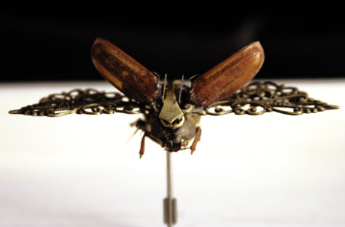
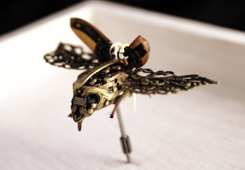
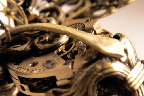
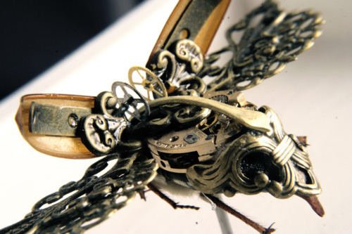
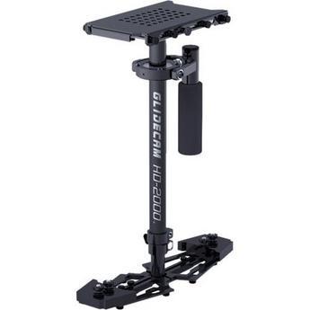
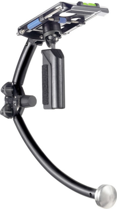
So here’s some merlin style steadicams other people have made
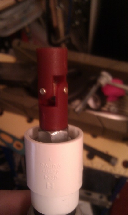
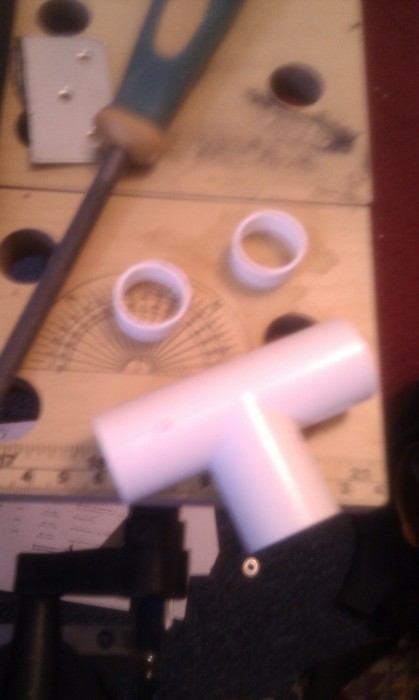
The one common element and the biggest pain in the ass from the previous project is the gimbal joint which is replaced in these models with a universal joint instead.So with no real design in mind i bought a universal joint from a hobby shop and set out to make one.
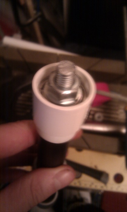
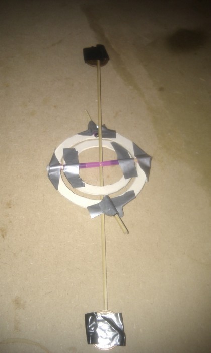
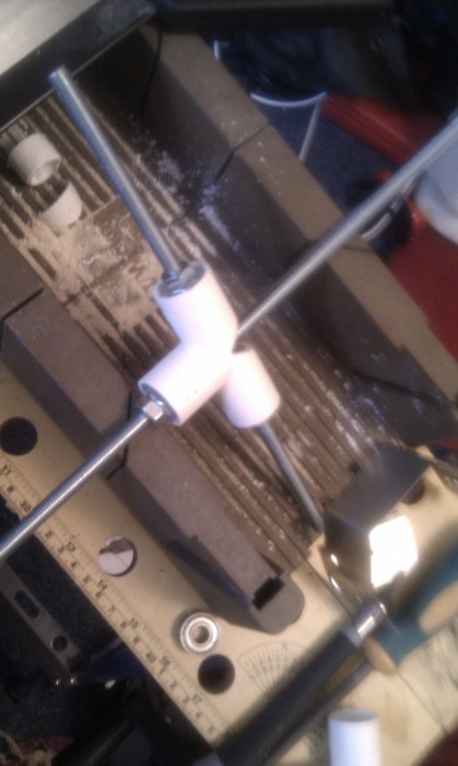
using some left over pvc pipe from my previous project i attached it to the top of an old desktop tripod and jammed a skate bearing in with some bolts to keep it in place, leaving some thread poking out to attach the universal joint to.
i wasnt too sure how to attach the universal joint so i just glued it hoping that the due to all the weight of the steadicam being on that point will be enough to keep it in place.
i cut down a bolt to be used for the bit that attaches the top of the universal joint to the rest of the steadicam, but this ended up not working, plans are for fools.
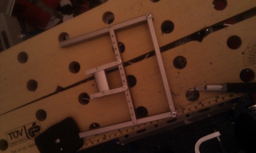
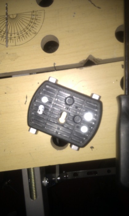
the main thing letting my previous steadicam down was the inability to adjust the cameras centre of balance so I started prototyping a way of being able to adjust the cameras position. The camera mount needs to be able to move on 2 axes of movement. My first design used pin holes which the base plate can move along on and be pined in place. This method isn’t too great due to only being able to move 1cm a time when 1mm can off balance the cam.
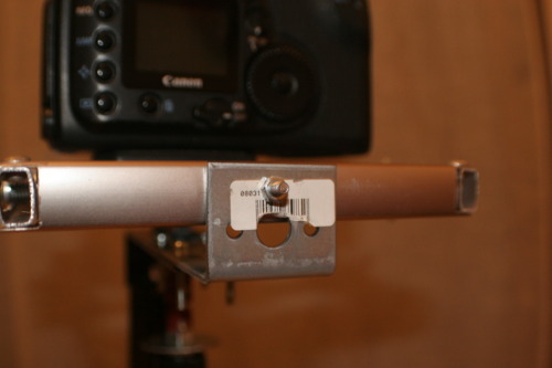
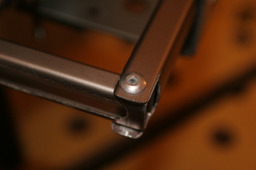
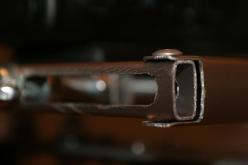
the main body of the steadicam is a mounting bracket for bikes or some shit and the other bit of metal which attaches the bike mount to the base plate is a joist bracket. I drilled and riveted these together so they are sturdy and strong like mother Russia. 
This is the two halves combined to make a whole, you then use the hole to escape the room. The adjustable base plate seems to be pretty good at adjusting. It is starting to look like a steadicam.
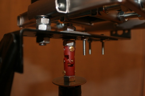
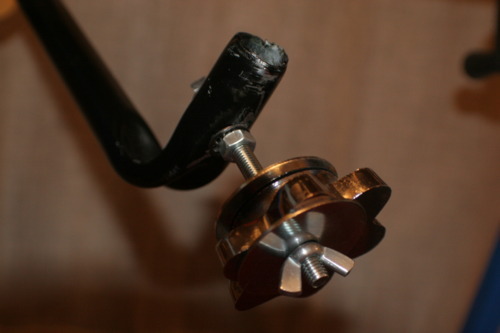
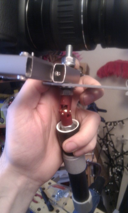
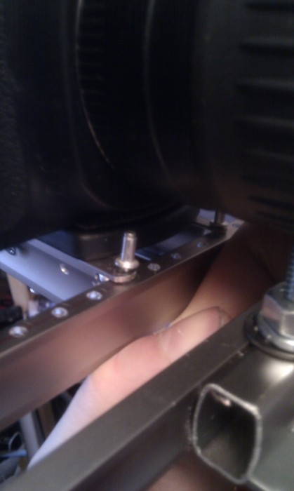
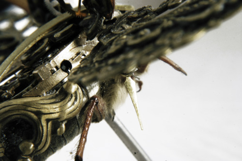
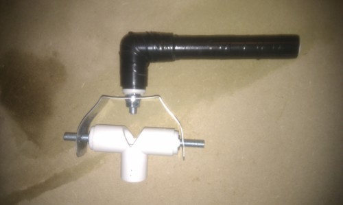
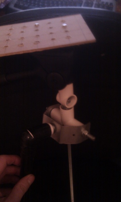
Detail showing the universal joint and the backwards wayi attached the adjustable splange to the rest of the steadicam.
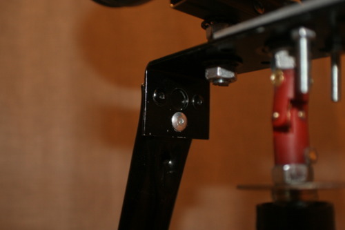
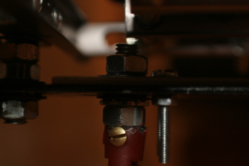
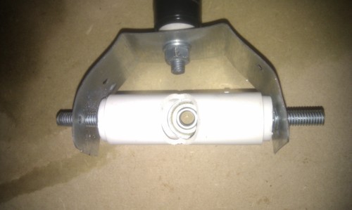
detail of the sketchy way the baseplate is attached to the adjustable doodah, at the moment it is held in place with un-riveted rivets but will be replaced with bolts.
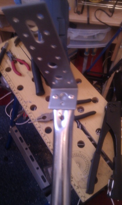
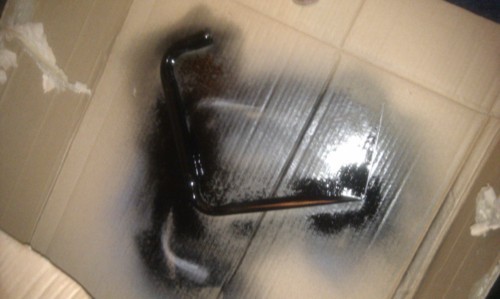
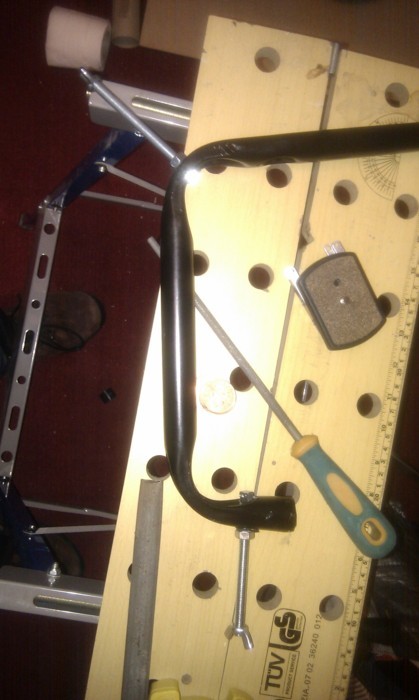
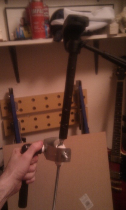
I sprayed the steadicam curvy bit black to give it a low radar signature
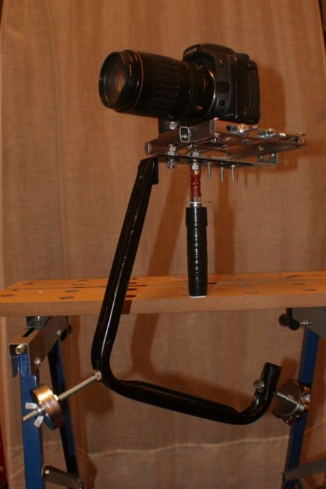
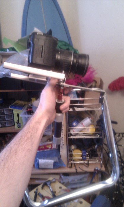
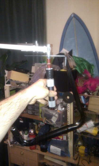
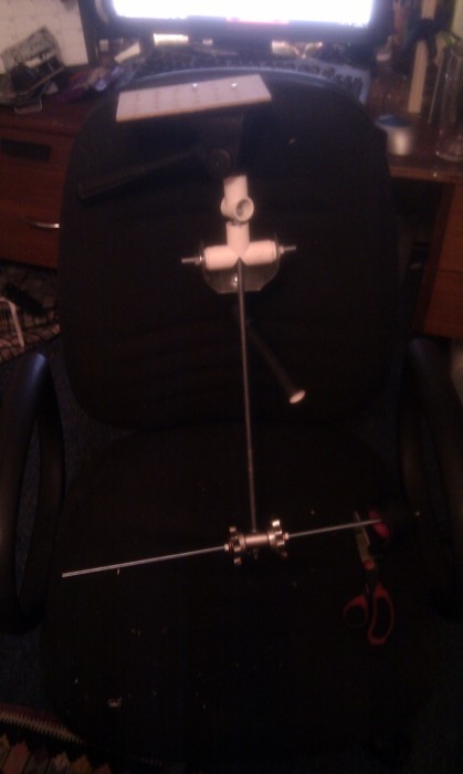
different angles of the steadicam as it stands. It still needs counter weights on the curvy bit and a better way of adjusting the base plate
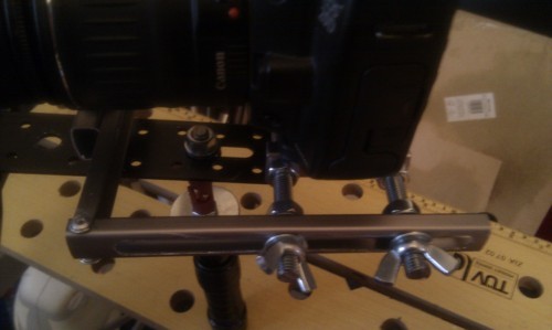
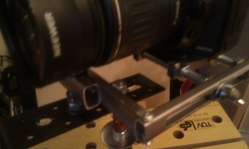
The curvy bit with bolts added for the counter weights, i kept them long so the weights can be moved closer to or further away from the main frame to adjust ballance.
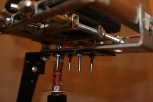
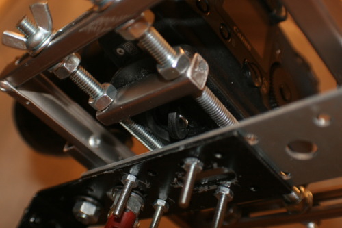
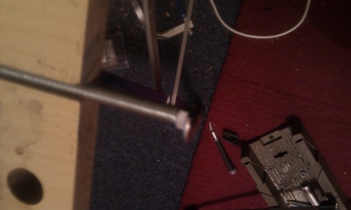
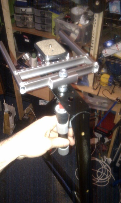
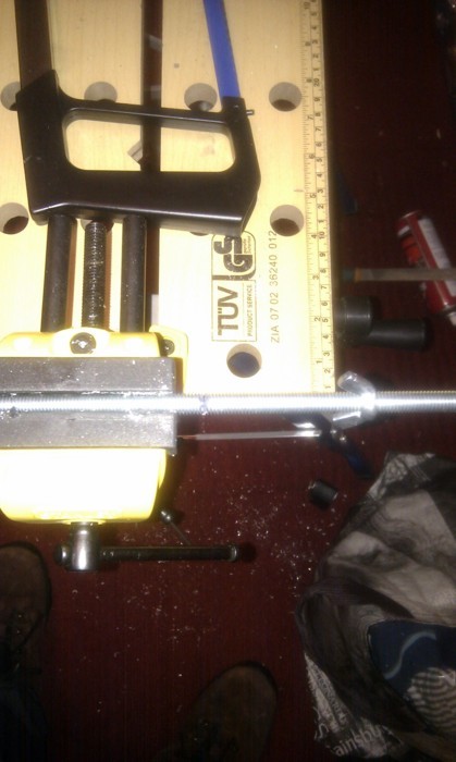
i started on a new adjustment system for the baseplate which will allow the millimetre presision it needs, the base plate has been screwed to two aluminium tubes drilled through 90 degrees to allow y axis movement.
the rails for the baseplate are threaded poles which are cut to length.
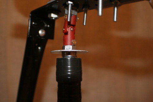
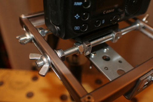
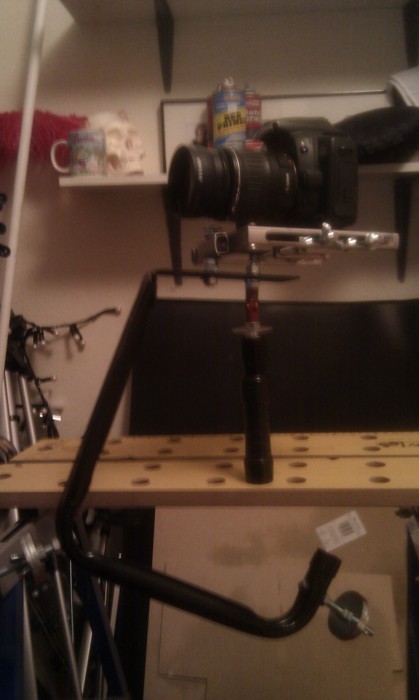
details of the new adjustable baseplate, it can now move as precisely as it needs to. Visible also just under the universal joint is a polished disk i added which allows you to control the pan of the camera smoothly, it being polished lets it slips with a soft grip keeping the movement smooth. 

Tuesday 26 April 2011

Clockborg Maybug

This is one of the steampunk Insects I have made, it started out as a real but dead may bug, now it is stronger, faster with 130% more electrolites. Also working on a scorpion but my girlfriend dropped it, so i fixed it but then I left hot chocolate in a flask for too long and it blew up (seriously!).....the smell....anywho suffice to say the scorpion is currently unwell as it was next to the flask when it exploded...If people like my steam punk stuff i shall post more, I have a rather splendid spider waiting to be shown


DIY steadicam

Due to Brass widow being filmed exclusively hand held i feel it’s important to use some kind of camera stabilisation. Last year while shooting Tempus Fugit we used a very ghetto camera stabilizer, a camera on a tripod held on the stem of the tripod at the centre of gravity. This worked OK but for my final 3rd year project I am keen to produce work to the highest standard. The film style could get away with not being stabilized due to the narrative but I like the type of shots glide cams produce, theres something a bit unatural about them and i feel this could add to the film, the hand held camera seems to almost fly hinting to the ghost waiting in the wings.
I started researching into ghetto steady cams, quite a popular is a very basic pole with weight at the end with your wrist acting as a gimbal. Bellow a few how to I found that use this method.
the problem with these is that they are heavy as shit and not that great, any jolt from the body gets transferred to the camera. I wanted to make a steadicam which isolates the movement from the body to the camera. One way of doing this would be to use a gimbal joint and suspend the body of the steady cam in it, the main downside to this however is gimbals are impossible to find or buy. 
I started designing gimbal joints beginning with a small scale model to use as a proof of concept
the main problem with this model was that it was totally shit and didn’t at all work, i knew gimbals work so i could only conclude that this didn’t work because the stars were incorrectly aligned for gimbal construction and not at all because i made it out of straws, duck tape and cocktail stick with tolerances put to shame by tectonic plate formation. After this great success failure i decided to do some research into what other people had made, and the design that stood out the most to me was based on the Glidecam 
montage! 
the best tutorial i found was the one bellow, the only problem is that there is only half of the tutorial so i would have to free style the rest of it
i followed the instructions ish and this is what resulted
this is the bracket i used for the gimbal mount
the tee joint and stoppers used for the gimbal
the gimbal with bearings and screw pole things
gimbal with handle
 
inside of gimbal showing bearing
gimbal handle with tripod top
inital tests with rig were impossible to ballance so i improvised an adjustable head out of mdf, the tripod top made the whole rig too top heavy so i cut it down and used a t joint to attach it to the main pole
completed rig, it works ok when balanced but looks pretty shit, i’m going to make another glidecam using what i have learnt from making this one and base it more on the merlin design of glide cam (pictured bellow)