
EXTREEEMLY STEADY TOM CAM 5 TO THE 25th
HOW STEADY IS STEADY? TURBO STEADY TECHNOLOGY KICKS YOU IN THE FACE WITH STEADINESS, EXTREEEM STEADY. STEADIER THAN A BOMB DISPOSAL EXPERT PLAYING OPERATION AGAINST A BRAIN SURGEON
So after some trials with my DIY Steadicam I’m now confident it’s finished, for now.
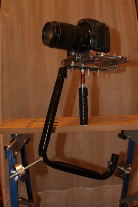
I had to make a few modifications after each test to resolve new problems that emerged each time.
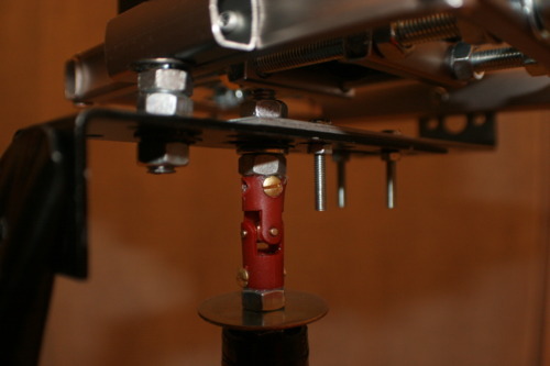
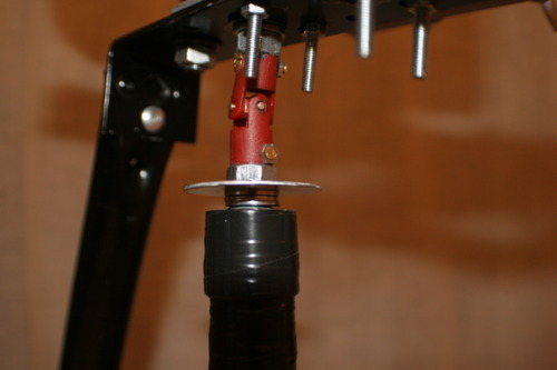
One thing i was previously unhappy was the attachment between the universal joint and the threaded bar. After Santa gave me some new metal drill bits i was able to drill through the universal joint and bar to bolt them together, this has stopped the slip that was occurring due to it only being glued. I will be looking for a Universal joint to replace the one i am currently using however as it just doesn’t feel very sturdy. Picture bellow showing universal joint and bolts holding the steadicam together
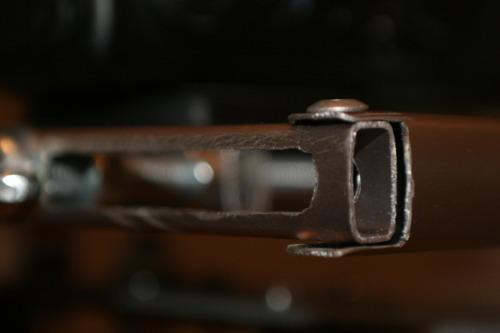
After the first test shoot it became apparent the rig was too flexible which created bounce in the video so i went about stiffening the whole design. The join between the bracket and the bike mount part was originally two rivets side by side but this allowed movement so i added a third larger rivet bellow the previous two to stiffen the join. The steadicam suffers a lot less from bounce here now.
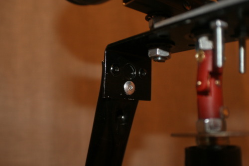
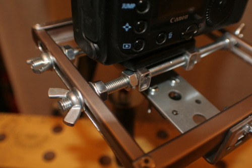
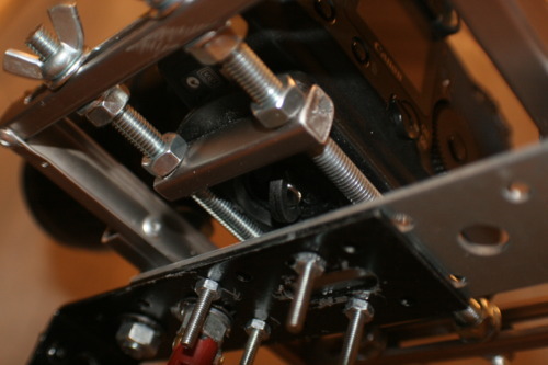
another problem creating bounce was the fact that the camera was attached to the main body of the steadicam by only one bolt mounted quite far forward, this created a spring like movement on the camera so i added another bracket and bolted it to the back of the adjustable plate to remove any movement arising from the join to the main body. Much of the DIY process has been learning as I go.
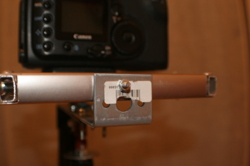
the two brackets didnt quite meet up so i had to drill new holes for the 4 bolts holding the two brackets together.
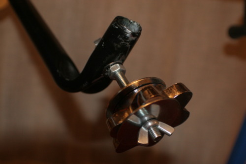
another addition i added previously was a slip ring that controls pan. I also replaced the handle with one length of pvc pipe, the previous handle made from a table top tripod kept slipping in its join and off balancing the steadicam.
Detail of the Adjustment mechanism, it had to perform 2 functions, move with millimetre precision and lock firm in place, as it stands it is for-filling both roles
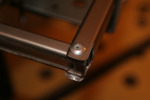
The Aluminium frame is made from the rest of the tri pod i took the baseplate from. I removed the legs and cut them to size, cut joints into them and riveted them for strength.
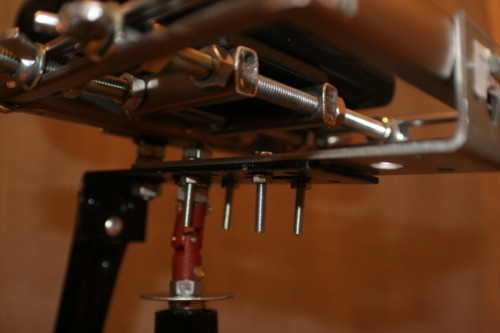
All the areas which are attached to threaded rod have locking washers on to minimize any movement ruining footage.
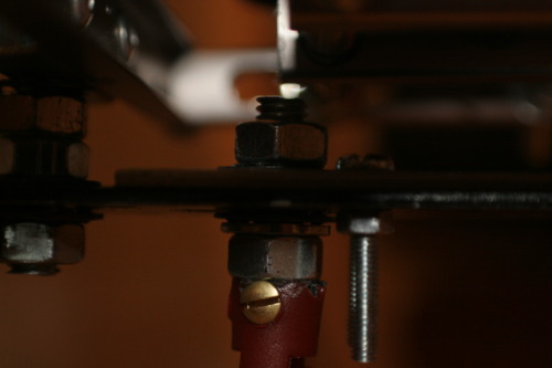
The weighting system involves long threaded bar so the weights can be moved up and down for fine tuning and also a heavy weight with a large centre hole enabling it to be weighted to either side to counter tilt on the camera
The camera screws directly to the base plate so it cant be easily removed, the plate must be moved right over to allow access which means the steadicam must be re balanced each time a camera is moved. This is a problem i hope to overcome in the future.
Quite a challenging part of the build was machining out the runners for the adjustable mount, i went through 4 grinding disks on my dremel doing this!
interesting!
ReplyDeletenice tutorial!
ReplyDeleteI know the weight is important to the performance of a steady cam unit: How heavy is the entire unit?
ReplyDeletelooks kinda ugly, so it should do the trick rite :D
ReplyDeleteI think I'm going to pass this along to a couple of my photographer friends. I don't even own a camera on my phone, much less a high powered camera in which to facilitate the need to have one of these.
ReplyDeleteBy the way, I liked your steadiness saying. I would like to see a bomb squad diffuser play operation against a brain surgeon. That would be the coolest.
I don't think it looks that bad .. it's fine and pretty useful
ReplyDeleteok this is super steady.
ReplyDeleteNice rig. I'm gonna need to build one soon i think.
ReplyDeletelooks solid :D
ReplyDelete